Hello everyone,
Lately, I have been working quite extensively with ModelingToolkit, particularly migrating some dynamic control models that I had previously implemented in various closed-source programs (often achieving significantly better performance with MTK by the way!). While I have verified that ModelingToolkit can indeed be used for this purpose without issue, I had never tried linking those control systems with electrical systems.
Yesterday, I began modeling a few simple electrical circuits with ModelingToolkit. At first, everything seemed to work correctly; however, I noticed a behavior that turns out to be rather inconvenient. I will describe it below through an example, as I believe that will make it easier to understand.
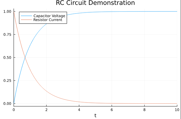
Let us take the RC circuit as an example, whose operation and construction are explained in RC Circuit · ModelingToolkitStandardLibrary.jl.
If we implement the circuit, the result is as expected — no issues arise, and the following equations are generated (as shown below).
using PlutoUI
using ModelingToolkit, Plots, OrdinaryDiffEq
using ModelingToolkit: t_nounits as t, D_nounits as D
using ModelingToolkitStandardLibrary
using ModelingToolkitStandardLibrary.Electrical
using ModelingToolkitStandardLibrary.Blocks


@mtkmodel RC begin

	@parameters begin

		R = 1.0
		C = 1.0
		V = 1.0

	end

	@components begin

		resistor = Resistor(R = R)
		capacitor = Capacitor(C = C, v = 0.0)
		source = Voltage()
		constant = Constant(k = V)
		ground = Ground()


	end

    @equations begin

        connect(constant.output, source.V)
        connect(source.p, resistor.p)
        connect(resistor.n, capacitor.p)
        connect(capacitor.n, source.n, ground.g)

    end
end

@mtkbuild sys = RC()

begin
	prob = ODEProblem(sys, Pair[], (0, 10.0))
	sol = solve(prob)
end
But what happens if we express the resistor as two resistors in series whose total value equals that of the original resistor? In principle, one would expect the system to behave the same, and therefore the resulting system of equations to be identical and to behave in the same way. However, when we define the model and generate the equations we can see that a new equation is created. Moreover, when solving the system the following error appears:
@mtkmodel RCAC2 begin

	@parameters begin

		R1 = 0.7
		R2 = 0.3
		C = 1.0
		V = 1.0


	end

	@components begin

		resistor1 = Resistor(R = R1)
		resistor2 = Resistor(R = R2)
		capacitor = Capacitor(C = C, v = 0.0)
		source = Voltage()
		constant = Constant(k = V)
		ground = Ground()


	end

    @equations begin

        connect(constant.output, source.V)
        connect(source.p, resistor1.p)
        connect(resistor1.n, resistor2.p)
		connect(resistor2.n,capacitor.p)
        connect(capacitor.n, source.n, ground.g)

    end
end

@mtkbuild sysAC2 = RCAC2()


probAC2 = ODEProblem(sysAC2, Pair[], (0, 10.0))
solAC2 = solve(probAC2)
“Cyclic guesses detected in the system. Symbolic values were found for the following variables/parameters in the map: resistor1₊v(t) => -0.3capacitor₊i(t) In order to resolve this, please provide additional numeric guesses so that the chain can be resolved to assign numeric values to each variable. "
This error can be easily solved by assigning initial values to one of the resistors. In this case, that is straightforward, but of course, in more complex circuits this becomes considerably more complicated. Moreover, I have verified through other examples that if the initial value does not match the actual value at the start, the system does not solve correctly. Given this situation, I wonder whether there is something wrong with my code (most likely due to my being a beginner in this area), or if there is something I am overlooking when modeling electrical circuits in ModelingToolkit. Obviously, in this particular case the issue is not serious, since the two resistors can simply be combined into a single one without any problem. However, in cases such as two transistors connected in series, this issue is not so easily avoided.
If possible, I would appreciate if someone could provide an explanation or offer some advice on how to prevent this behavior.
Thanks in advance.