2d plot in 3d scene

I would like to create a plot that contains two 2d heatmaps (XZ and YZ) but seen from a 3d perspective.

In spirit a similar to this view:
http://www.didaktikonline.physik.uni-muenchen.de/programme/dipolstr/DipoleRadiation.html?m=101001

But then also adding animated quivers in 3D.
Is this possible with the Plots.jl package?

I tried modifying the camera position of a 2d plot, but that seems to be ignored.
Any ideas how to embed 2d plots into a 3d scene?

Please check this example:

using Plots; gr()

const V = 2000

W(t, ϕ, θ) = V*t*[cosd(ϕ)*sind(θ), sind(ϕ)*sind(θ), cosd(θ)]
 
t, ϕ, θ = range(0, 0.1, 100),  0:3:90.0,  0:3:90.0

Exz = [[W(t, 0, θ) for θ in θ] for t in t]
Eyz = [[W(t,90, θ) for θ in θ] for t in t]
Exy = [[W(t, ϕ,90) for ϕ in ϕ] for t in t]

for (Exz, Eyz, Exy) in zip(Exz, Eyz, Exy)
    display(plot(getindex.(Exz,1), getindex.(Exz,2), getindex.(Exz,3), yflip=true, lims=(0,200)))
    display(plot!(getindex.(Eyz,1), getindex.(Eyz,2), getindex.(Eyz,3)))
    display(plot!(getindex.(Exy,1), getindex.(Exy,2), getindex.(Exy,3)))
    sleep(0.05)
end

spherical_wave

3 Likes

Thanks for the great code example! That look already pretty good. But its a curve and not a heatmap on the walls.
The other thing is that quivers seem to not support 3D arrows in Plots.jl. So maybe I should rather use GLMakie. It seems that they have a convenient volumeslices!() method that may be of help here.

Please check this:

using Plots; plotlyjs()

n = 100
x = y = z = range(0,10,n)

xx, yy, zz = x .* zeros(n)',  y .* ones(n)', z .* ones(n)'
surface(xx, yy', zz, fill_z = (yy').^2 + zz.^2)

xx, yy, zz = x .* ones(n)',  y .* zeros(n)', z .* ones(n)'
surface!(xx',yy, zz, fill_z = (xx').^2 + zz.^2, yflip=true)

xx, yy, zz = x .* ones(n)',  y .* ones(n)', z .* zeros(n)'
surface!(xx', yy, zz', fill_z = (xx').^2 + yy.^2, size=(800,800))

Animating such displays we can produce in Plots.jl:
Plots_plotlyjs_wave

5 Likes

This should work also, 3 observables, one per heatmap and just for fun a fourth one for one arrow.

using GLMakie
nt = 100
x = LinRange(0, π, nt)
y = LinRange(0, π, nt)
t = 1
hm1 = Observable(sqrt.(x .^ 2 .+ y' .^ 2) * t / nt)
hm2 = Observable(sqrt.(x .^ 2 .+ y' .^ 2) * t / nt)
hm3 = Observable(sqrt.(x .^ 2 .+ y' .^ 2) * t / nt)
colormap = :Hiroshige
colorrange = (0, 5)
transparency = true
# arrow
steps = 250
stretch = range(π, 0.65, length=steps)
δa = Observable(stretch[1])
ps = [Point3f(0.01, π, π)]
direction = @lift([Point3f(0.01, -π + $δa, -π + $δa)])

fig = Figure(resolution=(1200, 1200), backgroundcolor=(:white, 0.1))
ax = LScene(fig[1, 1]; show_axis=false)
meshscatter!(ax, [Point3f(0, 0, π), Point3f(0, π, π)], markersize=0.0) # forcing some fake limits
arrows!(ax, ps, direction; linewidth=0.02,
    arrowsize=Vec3f(0.16, 0.16, 0.25), transparency)
heatmap!(ax, x, y, hm1; transformation=(:xy, -0.0),
    colorrange, colormap, transparency)
heatmap!(ax, x, y, hm2; transformation=(:yz, -0.0),
    colorrange, colormap, transparency)
heatmap!(ax, x, y, hm3; transformation=(:xz, -0.0),
    colorrange, colormap, transparency)
fig

record(fig, "heatmap_planes.mp4") do io
    for t in 1:steps
        hm1[] = sqrt.(x .^ 2 .+ y' .^ 2) * t / nt
        hm2[] = sqrt.(x .^ 2 .+ y' .^ 2) * t / nt
        hm3[] = sqrt.(x .^ 2 .+ y' .^ 2) * t / nt
        δa[] = stretch[t]
        recordframe!(io)
    end
end

1 Like

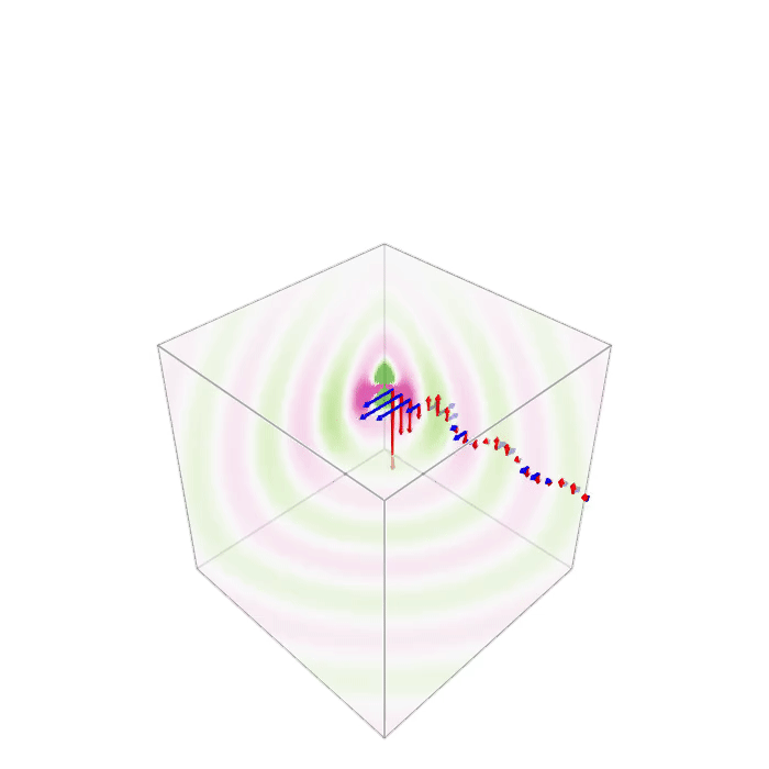
Thanks a lot for all the hints. Using Makie, I managed to do it with the volumeslices!() method. If you do this, you have to take care of calling plt[:update_xy] etc. Otherwise there will be no updates.
The animation part of the code (with observables defined for the data and the list of arrows) looks like this:

fig = Figure(resolution = (700, 700), backgroundcolor=(:white, 0.1));
ax = LScene(fig[1,1], clear=true, scenekw=(show_axis=false,), show_axis=false)  
maxcol=0.3
plt = volumeslices!(ax, x, y, z, dat, colormap=(:PiYG_5, 0.7), colorrange=[-maxcol,maxcol], transparency=true)
res = arrows!(qposX,qposY,qposZ,qdatEX,qdatEY,qdatEZ, color=:red, arrowsize=0.5); #
res = arrows!(qposX,qposY,qposZ,qdatMX,qdatMY,qdatMZ, color=:blue, arrowsize=0.5); #
fig
scene=ax.scene
cam3d!(scene)
scale!(scene, 0.07, 0.07, 0.07)
record(fig, "dipole3D_EM.gif", LinRange(0, 1, 50)) do t
    time[] = t
    plt[:update_xy][](1)
    plt[:update_yz][](1)
    plt[:update_xz][](1)
    # rotate!(scene, Vec3f(0, 0, 1), 0.5 * sin(2*pi*t/10))
end

dipole3D_EM

Here is an example for observable code:

time = Observable(0.0)
dat = @lift(real.(vol .* exp.(-1im .* 2 .* pi .* $time)))
qdatEX = @lift(real.(qdatEXC .* fac .* exp.(-1im .* 2 .* pi .* $time)))

1 Like

If you were looking for a Makie solution, you should not have asked for a Plots.jl solution.

I suggest you open a Makie thread with your new question and your own solution.

Sorry. I tried with Plots.jl for a while but then could not find a way to conveniently display 3d vectors.
Since I wanted it done, I switched to Makie instead. So yes, I was looking for a Plots.jl solution at first.
The part you posted using Plots.jl is anyway quite interesting!